What is MPO Breakout Cables?
POSTED ON 15/08/2022 BY TOM

Introduction
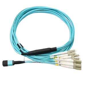
MPO break out cables are used to connect from an MPO system to LC duplex connectors. According to a document from ANSI/TIA, the breakout of an MPO cable from ribbon fiber to discrete fiber is neither defined nor standardized. The MPO-LC break-out cablesdesign can be quite complex due to limitations in the MTP® connector and the LC plug. These challenges require complex routing of fibers inside the connector backshell or fan-out housing, difficult insertion and polarity management, stiff cable assembly and the need for a protective boot.

MPO Breakout Cables
Understanding MPO Breakout Cables
MPO Breakout Cables are used to connect from an MPO system to LC duplex connectors. According to a document from ANSI/TIA, the breakout of an MPO cable from ribbon fiber to discrete fiber is neither defined nor standardized. The role of this cable is simply to convert a multi-fiber connection into one or more individual connections which can then be terminated with LC duplex connectors. They can also be used for multiplexing/demultiplexing applications.
MPO breakout cablesare used to connect from an MPO system to LC duplex connectors.
MPO breakout cables are used to connect from an MPO system to LC duplex connectors. They can be used in fiber optic applications such as networking, telecom and data centers where fiber channel technology is utilized. These cables should be used with a variety of fiber optic devices including patch panels, GBICs, LC/MU adapters and transceivers. The MPO connectoris often referred to as a “mini SC” or “multipin.”
According to a document from ANSI/TIA, the breakout of an MPO cable from ribbon fiber to discrete fiber is neither defined nor standardized.
According to a document from ANSI/TIA, the breakout of an MPO cable from ribbon fiber to discrete fiber is neither defined nor standardized.
This is not surprising since there are many different types of breakout technologies. The most common one is called mechanical splice and it uses a tool called fusion splicer in order to make connections between fibers in an active way by melting the materials together. This means that each strand inside the ribbon must be melted with its neighbor before they come out as individual fibers, which requires heat and pressure. On other occasions, you can use a so-called mechanical splice adapter that basically lets you connect two individual fibers without melting them together through thermal fusion; this makes for more compact connectors but also adds complexity because these adapters require additional alignment pins in order for them not slip out during installation or removal processes.

The MPO-LC break-out cables design can be quite complex due to limitations in the MTP® connector and the LC plug.
The MPO-LC break-out cables design can be quite complex due to limitations in the MTP® connector and the LC plug. The MTP® connector is not designed to be used with LC connectors. In addition, an LC plug can only accept one fiber per side of the faceplate, which leaves three additional fiber strands that must somehow pass through when connecting to an MTP® connector.
These challenges require complex routing of fibers inside the connector backshell or fan-out housing, difficult insertion and polarity management, stiff cable assembly and the need for a protective boot.
Insertion loss challenges usually caused by high-density configurations of fibers inside the connector backshell or fan-out housing. Also designs that force the MPO connector ferrule into a very tight radius bend may affect performance.
Polarity management and performance requirements can be difficult to meet with flexible cables in the field, especially when using patch cord connectors that have limited bend radii. With new applications requiring even tighter bend radius requirements, it becomes increasingly challenging to achieve good polarity management for these types of cables without going through an expensive re-wire process in order to make changes down the line if necessary.
Fiber protection booting material is typically made from nylon or polyvinyl chloride (PVC) which is not ideal due to its susceptibility to damage and wear over time when exposed under harsh environments such as outdoors or areas where there are heavy vibrations due to equipment being installed near moving vehicles etc..
The following are common challenges with MPO-LC break out cables:
Insertion loss (power or signal)
Polarity management – Single mode fibers have different core and cladding diameters, which means that light is refracted at different angles when entering or exiting the fiber. If a patch cord is not properly terminated and/or installed, it can result in significant loss of power through reflections.
Fiber routing – Inadequate fiber routing may cause increased attenuation due to bending losses.
1. Insertion loss challenges usually caused by high-density configurations of fibers inside the connector backshell or fan-out housing . Also designs that force the MPO connector ferrule into a very tight radius bend may affect performance.
Insertion loss challenges usually caused by high-density configurations of fibers inside the connector backshell or fan-out housing. Also designs that force the MPO connector ferrule into a very tight radius bend may affect performance.
2. Polarity management challenges when two different connectors were used for MTP® (MPO) and LC. Two connectors have different key positions which means they use different polarity methods as well. This is especially true when pre-terminated cables are used.
When using a pre-terminated cable, polarity management becomes very important. The reason for this is that each connector has a different key position and uses different polarity methods. This can cause problems when using both an MTP MPO and LC connector on the same cable as they may not be terminated with the correct polarity.
The two most common connectors used in today’s fiber optic networks are the MTP® (MPO) and SC/APC connectors. Both of these types of connectors use very different methods to terminate fibers within them so they cannot be easily interchanged between each other without causing issues with data transmission speeds or even worse, causing damage to equipment such as routers or switches due to poor quality signals being transmitted through them!
This is why it’s so important for anyone working in this field not just know how these cables work but also how using different types together could cause problems down the line!
3. Fiber routing challenges due to limited space inside the backshell or fan-out housing
The third category of fiber routing challenges is due to limited space inside the backshell or fan-out housing. The size of the opening in these housings is often very small, making it difficult to insert and manage the cables. Many times, a stiff cable assembly and the need for a protective boot are also common issues associated with this type of installation.
Conclusion
In conclusion, the MPO-LC break-out cable design is a complex one. The following are common challenges with MPO-LC break out cables
Insertion loss challenges usually caused by high-density configurations of fibers inside the connector backshell or fan-out housing . Also designs that force the MPO connector ferrule into a very tight radius bend may affect performance.
Polarity management challenges when two different connectors were used for MTP® (MPO) and LC. Two connectors have different key positions which means they use different polarity methods as well. This is especially true when preterminated cables are used
Fiber routing challenges due to limited space inside the backshell or fan-out housing .
Contact: Andy Huang
Phone: 0086-755-89239407
E-mail: sales@beskco.com
Add: No.3106,Longgang Avenue,Pidi Town, Longgang District, Shenzhen China
We chat